SinterPixels Demos Part 4: A Randomly Asymmetric Leaf
My new app, SinterPixels, is in the App Store. For the fourth installment in the series of examples of what one can do with SinterPixels, let’s revisit yesterday’s post, where we explored how to draw a simple, symmetric leaf. Today, we’ll expand on that simple leaf, and make it a bit more organic, by introducing some randomness in the parameters we use for drawing the lines.
First, lets introduce a function that gets a random number between -1.0 and 1.0:
to randomFraction()
return (random number from -100 to 100) / 100.0
end randomFraction
Next, lets write a function that makes the anchor data and color for a single line that we use to draw a leaf – we’ll draw 11 of these
to leafPath(tip, px, py, slp, col)
using terms from application "SinterPixels"
set p1 to {position:{0, 0}, slope:slp}
set p2 to {position:{px, py}, slope:0}
set p3 to {position:{tip, 0}, slope:0}
return {pts:{p1, p2, p3}, clr:col}
end using terms from
end leafPath
When we call this function, we pass in 5 values. tip is the length of the leaf, in pixels. px is x value at the highest (or lowest) point on the arc – where the slope of the path is zero. py is the y coordinate at that point. slp is the slope of the line where the path begins, on the left. and col is the color. This function returns the basic information needed to draw a single path, of which we’ll draw 11 to make a leaf shape.
Now, let’s write a function that will generate all 11 of our paths for a leaf. This function will need a bit more info. The tip and px values are the same as in the previous function. But now, the topmost and the bottommost paths will have different values, a py (positive y) value and a ny (negative y) value. Yesterday, in our symmetric leaf, py and ny were both just the same as px. And, we need two slopes, one for the top path (pSlp) and one for the bottom path (nSlp) . Yesterday, the slopes were 1 and -1, which made things simple:
to allLeafPaths(tip, px, py, ny, pslp, nSlp)
set topLeafPath to leafPath(tip, px, py, pslp, {0.1, 0.7, 0.1})
set bottomLeafPath to leafPath(tip, px, ny, nSlp, {0.1, 0.7, 0.1})
set centerLeafPath to leafPath(tip, px, (ny + py) / 2, pslp + nSlp, {0.25, 0.8, 0.25})
set allPaths to {topLeafPath, centerLeafPath, bottomLeafPath}
repeat with n in {1, 2, 3, 4, 6, 7, 8, 9}
set m to 10 - n
set minorPath to leafPath(tip, px, (n * ny + m * py) / 10, (m * pslp + n * nSlp) / 10, {0.6, 1.9, 0.6})
set allPaths to allPaths & {minorPath}
end repeat
return allPaths
end allLeafPaths
Here, we make three paths special – the top, center and bottom paths. Then, in the loop, we create eight paths evenly spaced between them – four between top and center, four between center and bottom.
Next, we need a function that will call into that allLeafPaths() function, supplying values with a little bit of randomness tossed in. Here’s how we do that:
to leafPathsWithRandomParams(sz)
set quarterSize to sz * 0.25
set dpy to quarterSize * 0.3 * (my randomFraction())
set dny to quarterSize * 0.3 * (my randomFraction())
set dx to quarterSize * (my randomFraction())
set py to dpy + quarterSize
set ny to dny - quarterSize
set tip to sz + dx
set pSlope to py / quarterSize
set nSlope to ny / quarterSize
return my allLeafPaths(tip, quarterSize, py, ny, pSlope, nSlope)
end leafPathsWithRandomParams
The three values, dpy, dny and dx are ‘delta’ values – that’s how much we are going to change the path anchor positions by. The two slope values are set based on the randomized py and ny values.
And, almost at the end, we write a function that actually calls leafPathsWithRandomParams() and draws the paths. This function draws all the paths at the position specified
to makeALeaf(pos)
tell application "SinterPixels"
tell document 1
set myPaths to my leafPathsWithRandomParams(260)
repeat with nthPath in myPaths
make new path with properties {position:pos, anchor data:pts of nthPath, closed:false, fill color:clear, color:clr of nthPath}
end repeat
end tell
end tell
end makeALeaf
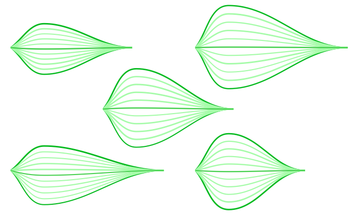
Now, to show off that each leaf is its own special someone, lets draw five of them, each at a different position, and see how they differ:
makeALeaf({-340, 120})
makeALeaf({20, 120})
makeALeaf({-160, 0})
makeALeaf({-340, -120})
makeALeaf({20, -120})
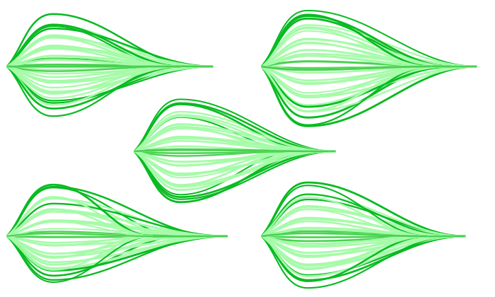
To generate the image like the one at the top of this post, just run that in a loop 5 times:
repeat 5 times
makeALeaf({-340, 120})
makeALeaf({20, 120})
makeALeaf({-160, 0})
makeALeaf({-340, -120})
makeALeaf({20, -120})
end repeat